We explain some basic technical terms that companies use in articles and spec sheets to describe the performance of their mobile mapping systems.
If you’re new to mobile mapping, you might be unfamiliar with the technical terms that companies use in articles and spec sheets use to describe the performance of their systems. Since this can make it difficult to understand how one tool differs from another in areas like accuracy and workflow, this article aims to help by explaining some basic terms.
We’ll cover the two kinds of accuracy used to benchmark a mobile mapping system, the accuracy errors that are common to mobile mapping devices and finish up by exploring the types of error-correction used in mobile mapping workflows. (We’ve also included a few links to articles that explain these topics in more depth.)
Accuracy terms
Local (relative) accuracy
The accuracy of a point cloud on a local scale. For a mobile scanner, this is the accuracy of a measurement between points in a single location like a room.
The metric is important in determining the reliability of a scanner, because it can show how accurate the dimensions of a room are—an important consideration for applications like scan-to-BIM or generating floor plans.
Global (absolute) accuracy
The accuracy of the point cloud on a global scale. For a mobile scanner, this is the accuracy of a measurement between two points that were not captured by the scanner in a single location. For example, the distance between opposite corners of a building.
Global accuracy is crucial when determining the reliability of a mobile scanner, because it highlights the amount of drift error that accumulates in large or complex mapping projects. In other words, it gives an indication about the scanner’s accuracy across the whole building.
It is also known as absolute accuracy, since it indicates the accuracy of the point cloud measurements as compared to their “true” position in an absolute coordinate system determined by a higher order method, like GPS or survey.
For more precise definitions for these terms, and more details about how NavVis measured this metric for its own scanners, see the NavVis VLX Accuracy White Paper.
SLAM error terms

Tracking error
When the simultaneous localization and mapping (SLAM) algorithm in the mobile scanner mis-calculates your position while recording your trajectory. This is most likely to occur when a space lacks the physical features the SLAM’s computer vision technology uses to make location estimates. For example: long, straight corridors are the most common causes of this error, because they lack doorways, windows, and corners.
Tracking errors are more common with less robust SLAM algorithms but can still present a challenge with the most advanced systems. They can be corrected using loop closure or control point optimization, when available.
Tracking errors are a primary cause of drift. (See below.)
Drift
When the trajectory data generated by your SLAM algorithm diverges from your true path as you scan. It results from the accumulation of smaller errors, such as tracking errors, or positioning errors that arise from sensor noise.
Drift is rarely a problem in short scans but becomes more likely the longer you scan. It is easy to see in the data, for example, when a straight corridor looks bent or a stairway is twisted.
This error can be reduced by more robust simultaneous localization and mapping (SLAM) algorithms, but it is nearly impossible to eliminate without extra measures. As a result, many vendors offer workflow features like loop closure or control points to correct for drift.
To find out more about how tracking errors and drift happen, and what you can do to correct for them, check out this post.
Error correction terms

Loop closure
A workflow feature that corrects for drift. It is offered by most mobile mapping systems.
To perform a loop closure, return to an area you have already scanned. The simultaneous localization and mapping (SLAM) algorithm will recognize the position and use it to calculate how much its trajectory has drifted since it was last there. This gives the algorithm all the information it needs to remove that drift and improve the quality of your final point cloud.
Control point optimization
A workflow feature that corrects for tracking errors or drift. It is primarily useful in larger projects where drift is more likely. Only the most advanced systems on the market offer this feature.
The most common implementation of control point optimization requires placing survey targets around the areas where errors are likely to occur and surveying the points with a total station. When you enter the coordinates for these targets into the scanner’s post-processing software, it uses this data as a control to optimize the point cloud and reduce errors.
For example, you might place checkerboard survey targets at either end of a long corridor to correct for tracking errors. Or you might place a number of targets throughout a larger scan project to correct for drift.
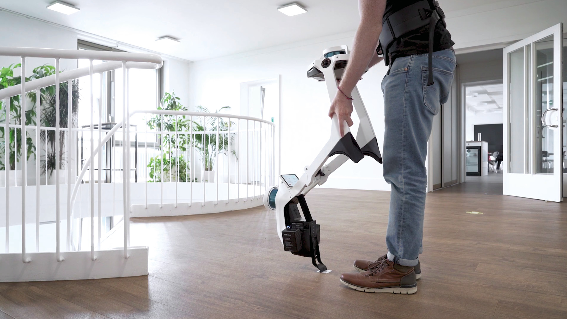
NavVis’ unique implementation also uses control points to verify global (absolute) accuracy as you scan. To use this function, place a control point, survey it, and touch it with the scanner as you pass. The interface will show the delta between the survey coordinates and the system’s position estimate, giving you insight about anything that might have gone wrong during the scanning process.
Learn more about SLAM errors and what you can do to correct them.
Control points
Survey targets such as checkerboard stickers or spheres.
Their most common use in scanning is for registering together point clouds generated by different methodologies, like mobile scanners, terrestrial laser scanners, and UAVs. For this application, capture the control point in two or more data sets in the area where they overlap. This provides the post-processing software a control during its registration process for ensuring that all data sets are combined precisely.
A second use of control points is error correction in mobile scanning workflows (see above on control point optimization for more information on this application).
Wrapping up
Those are a few of the basic ideas that you’ll need to understand to make an informed decision when shopping for a mobile mapping system.
Now, you should have the tools to determine how accurate a scanner is in a local setting, as well as across the entirety of the project. You will also be prepared to ask questions about how drift and tracking errors affect a scanner’s accuracy, and which tools the manufacturer includes to correct those errors.
In other words, you should be ready to determine how one mobile mapping system performs when compared to another, and to choose a system you can rely on.
Sean Higgins is an independent technology writer, former trade publication editor, and outdoors enthusiast. He believes that clear, buzzword-free writing about 3D technologies is a public service.


